Shape Graphics
You can use the Shape Graphics form (Workspace > Tools > Shape Graphics) to modify the graphical display of point sets, polyline sets, markers and microseismic data (the latter is also represented by a point set). Note that some basic settings (such as color or size) are also available through an object's context menu (under 'Properties > Set active property' and 'Display Settings') and via the object's Property Inspector ( ), but the Shape Graphics form provides some additional functionality (e.g. using directional component properties to display shapes with orientation).
The form is intended for the 3D View and 2D View; other views (such as the Seismic View or Cross Section View) are not fully supported by the Shape Graphics functionality. When you alter a setting on the form, the object's display is instantly updated in the view.
 or you can import an existing template using the import button
  .
.Type Select the type of geometric representation (i.e. polyline set, point set or marker) or microseismic data from the drop-down list to populate the table below. All representations of the selected type that exist in your solution will be listed. In the table, select the representation (one or multiple) for which you want to alter the display.
Set shape color and size You can change the color and node size using the drop-down lists. In the Node size entry field you can either type in a value, or use the arrows to adjust the size.
Set shape property Selecting a property from the Shape type drop-down will graphically (via color or size) apply the property value to the nodes or markers. Example: display markers with Depth as property. In case you selected multiple representations in the table, only properties that exist for each representation are available for selection.
Set shape type and size This option sets the shape and size of markers and nodes of a point set or polyline set, for instance to 'coin' or 'arrow'.
- Shape type Select the shape in which you want to display nodes or markers. For more information on Beach Ball, see How to read the Beach Ball orientation. For more information on Tensor, see Using Tensor as Display Type.
- Size % Refers to the size of the shape in the lateral direction. Default is 100%. Select a smaller or larger size if required.
- Thickness Refers to the size of the shape in the vertical direction. Default is 100%. Select a smaller or larger thickness if required.
- Reset Click the reset button
 to reset the shape type, size and thickness to the default settings.
Set shape scale Only enabled when 'shape type' is not set to 'Default'. With this option you can scale the size of the shapes with respect to a property. Scaling can be applied in all directions at once, or in X, Y or Z direction separately. Example: display the shapes scaled according to depth. The shapes at a shallow depth will be shown smaller than shapes at a greater depth.
- Scale object Select the property that you want to use to scale the size of the shapes. The higher the property value, the larger the shape. All properties of the selected object are available for selection. When using this option, the shape is scaled with the same amount in all directions, giving the same result as when you select the same property in the X, Y and Z direction. Certain properties may have values in negative scale but the absolute magnitude of the vectors is more significant in such cases (e.g. for displacement property scalar value of '-10' is smaller than '2' but the absolute value will indicate that the displacement of '-10' is more than '2'). Click on the adjacent icon
 to Create absolute property for the property selected in the field. The new property is named with '_Absolute' and also stored in the JewelExplorer for the selected object. The figure below shows the difference between the shape graphics of a property and the respective absolute values for the same property.
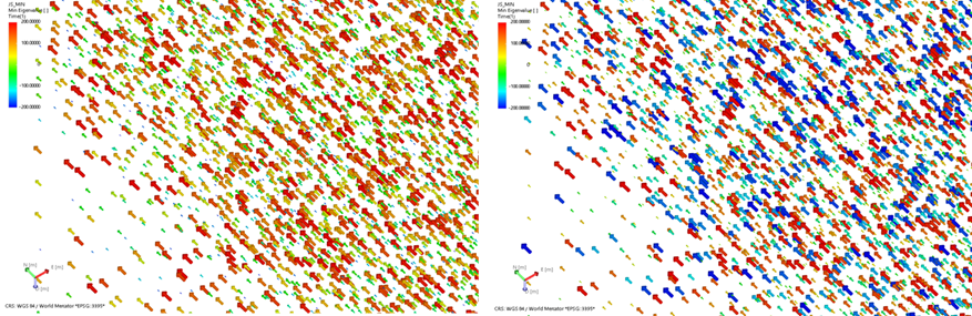
The image on the left side shows the scale with negative values in blue while the positive values in red. On right side, the absolute values of the same property are shown. click to enlarge
- Scale X Select the property that you want to use to scale the size of the shapes in the X direction. The higher the property value, the larger the shape in the X direction. All properties of the selected object are available for selection.
- Scale Y Select the property that you want to use to scale the size of the shapes in the Y direction. The higher the property value, the larger the shape in the Y direction. All properties of the selected object are available for selection.
- Scale Z Select the property that you want to use to scale the size of the shapes in the vertical direction. The higher the property value, the larger the shape in the vertical direction. All properties of the selected object are available for selection.
- Reset Click the reset button to remove scaling from the shape.
Set shape orientation Only enabled when 'shape type' is not set to 'Default'. With this option you can give an orientation to the shape. For example, you can make 'one-sided arrows' (selected under 'Shape type') to point in a certain direction. You can do this using properties of type 'dip' and 'dip azimuth', or based on a vector by using properties representing the Easting, Northing and Depth direction (for which all property types can be used).
Azimuth and dip
- Azimuth (GN) Select a property of type 'dip azimuth' to orient the shape with an azimuth (angle with Northing direction).
- Dip Select a property of type 'dip' to orient the shape with a dip. For beach balls the dip is displayed along the strike direction, see How to read the Beach Ball orientation.
- Rake Select a property to orient the beach balls with a rake.
Vector (not in combination with beach ball as a shape)
- Northing component Select a property that represents the Northing component of the orientation. All property types can be used.
- Easting component Select a property that represents the Easting component of the orientation. All property types can be used.
- Depth component Select a property that represents the Depth component of the orientation. All property types can be used.
- Reset Click the reset button to remove the orientation from the shape.
Tensor (only available when the shape type is set to tensor)
Required input is the Tensor (JewelSuite) convention. For each of the listed tensor components, select the appropriate property from the drop-down list. If your input data is not in the Tensor (JewelSuite) convention, you can use the Convert Tensors form to convert property values from one convention to the Tensor (JewelSuite) convention.
- SNN Select a property that represents the NN component.
- SNE Select a property that represents the NE component.
- SND Select a property that represents the ND component.
- SEE Select a property that represents the EE component.
- SED Select a property that represents the ED component.
- SDD Select a property that represents the DD component.

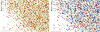
Graphical representation of the input tensor components in the JewelSuite coordinate system. The first letter indicates the plane; the second letter indicates the direction click to enlarge
Tensor component visibility
By default, the maximum, medium and minimum components are selected for display The tensor components are scaled automatically taking the entire tensor along (meaning that the smaller values also return a smaller arrow, etc.). You can uncheck a checkbox to hide a component from the view. You can change the colors using the arrow next to the color box. It will open a dialog where you can select a color of your liking.
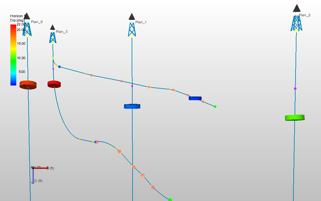
An example where markers are displayed as coins, the shape property is set to 'depth' click to enlarge
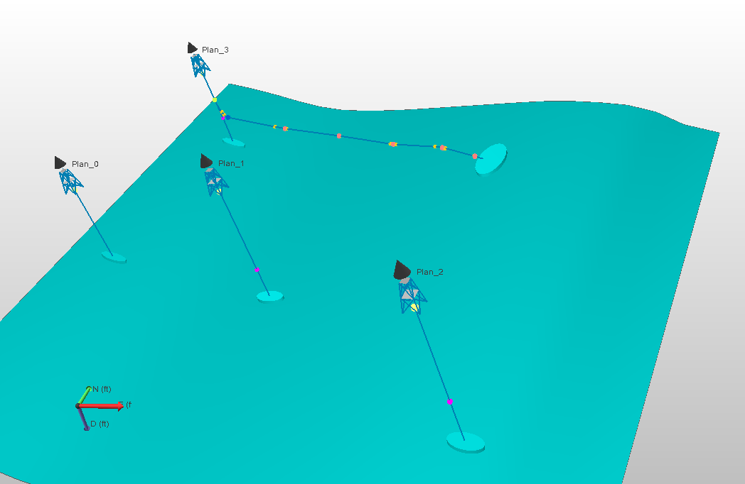
As picture above, with surface. click to enlarge